I. Experimental Scenario: Morphology Observation of Spindles during Cell Division
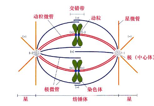
1. The spindle apparatus is a special organelle formed from prophase to telophase of cell division. Its major components include microtubules, microtubule‑associated molecular motors, and a series of complex supramolecular structures.
Figure 1: Schematic diagram of spindle structure
2. Cell division refers to the proliferation of living cells, whereby one cell divides into two daughter cells. It serves as an essential mechanism for biological growth and reproduction. During cell division, chromosomes — the primary carriers of genetic material — undergo orderly rearrangements to achieve proper segregation. This ensures accurate transmission of genetic material from mother cells to daughter cells, guaranteeing normal biological growth, development as well as species continuity and stability.
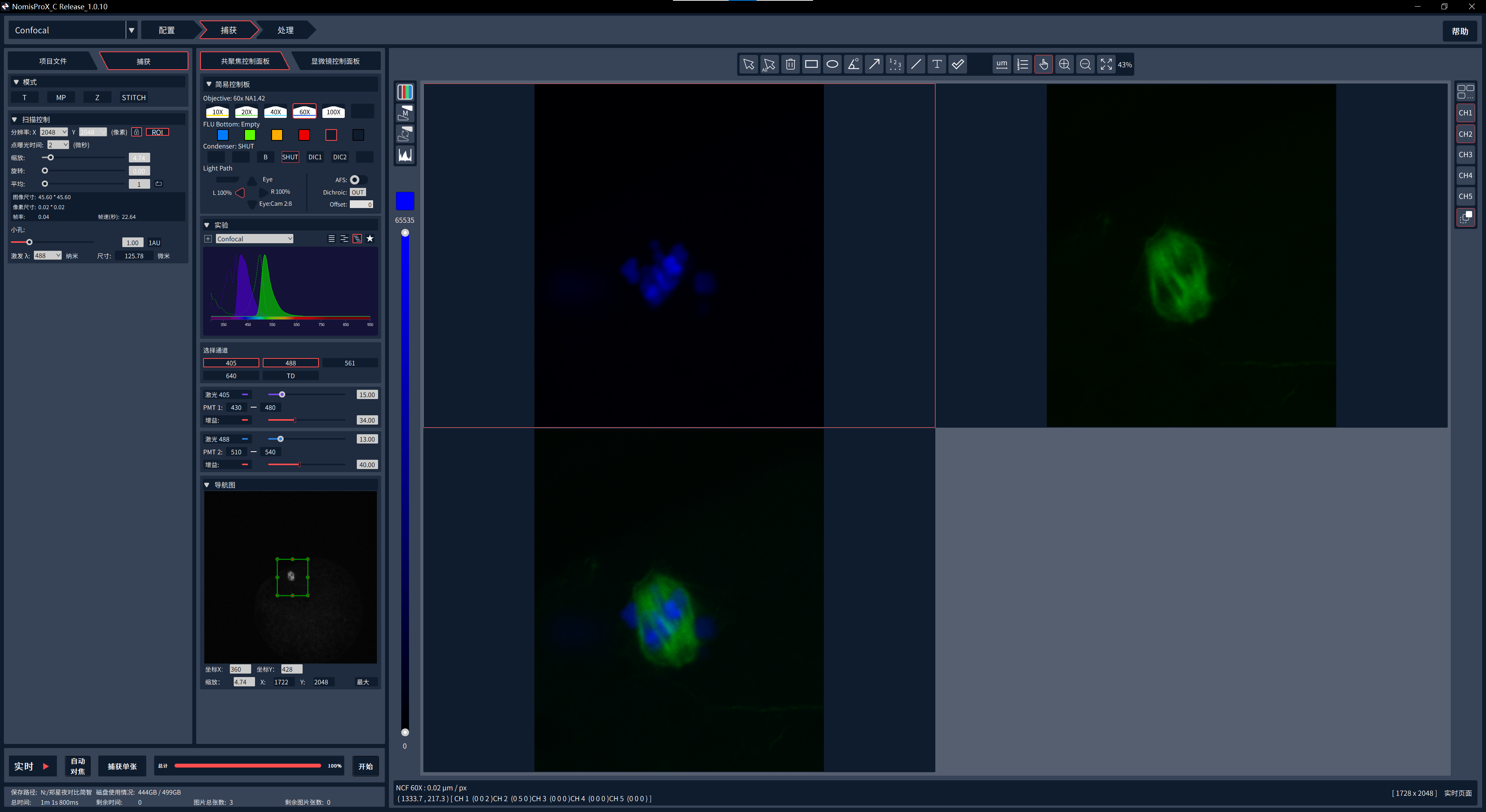
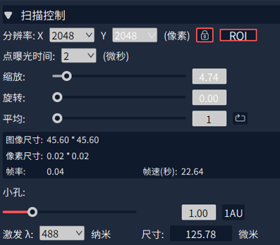
3. In this experiment, users adopted the ROI tool of the NCF1000 laser confocal microscope to precisely magnify spindles. By observing the relative positions and morphological changes of spindle microtubules and nuclear proteins in oocytes, the regulatory role of spindles in reproductive development can be determined.
Figure 2: Software interface of ROI partial magnification on NCF1000 laser confocal microscope
- Morphological Observation of Oocyte Spindles via ROI Partial Magnification
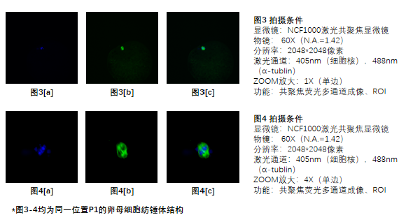
Under a 60× objective lens (1.42 N.A., Oil), the oocyte spindle appears only rice‑grain‑sized (Figure 3), making it difficult to resolve the relative positions and dynamic changes of microtubules and nuclear proteins. To clearly observe spindles measuring merely 20 μm, the ROI tool of NCF1000 laser confocal microscope enables precise observation of target regions (Figure 4).
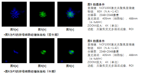
During the experiment, distinct variations were observed in microtubule morphology and nuclear‑protein abundance of oocyte spindles throughout cell division, which further influence reproductive regulation. Figure 5 shows prometaphase: multiple centrosomes and reticular‑patterned microtubules. Figure 6 shows metaphase, featuring generally symmetric microtubule distribution and markedly reduced nuclear‑protein content.
II. How NCF1000 Confocal Microscope Facilitates the Experiment
1. ROI Partial Magnification Function
- ROI (Region of Interest) denotes a designated area within an image or video for focused observation or processing (Figure 7).
- The ZOOM function magnifies the central field‑of‑view and represents a special ROI application.
- Supported by the bundled NomisPro X‑C software, NCF1000 laser confocal microscope delivers an additional 4× magnification on top of the 60× oil‑immersion objective for high‑clarity fluorescence imaging (Figure 8).
Figure 7: ROI‑function interface
Figure 8: Image display interface with ROI function enabled
2. Image Filtering Function
image‑processing technique for noise reduction and feature enhancement. Filters fall into linear and nonlinear categories. Linear filters include mean filtering and Gaussian filtering; nonlinear filters cover median filtering and bilateral filtering.
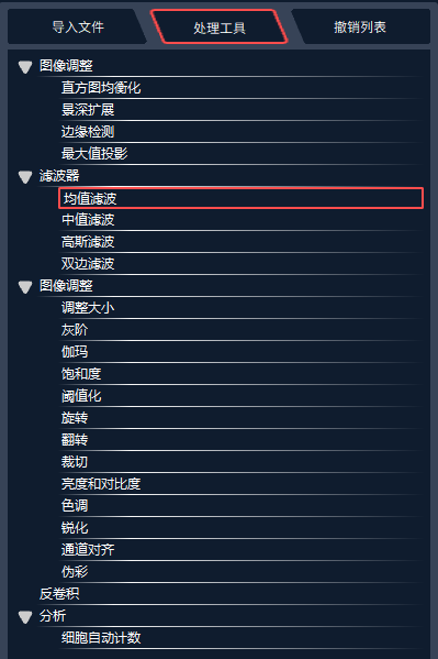
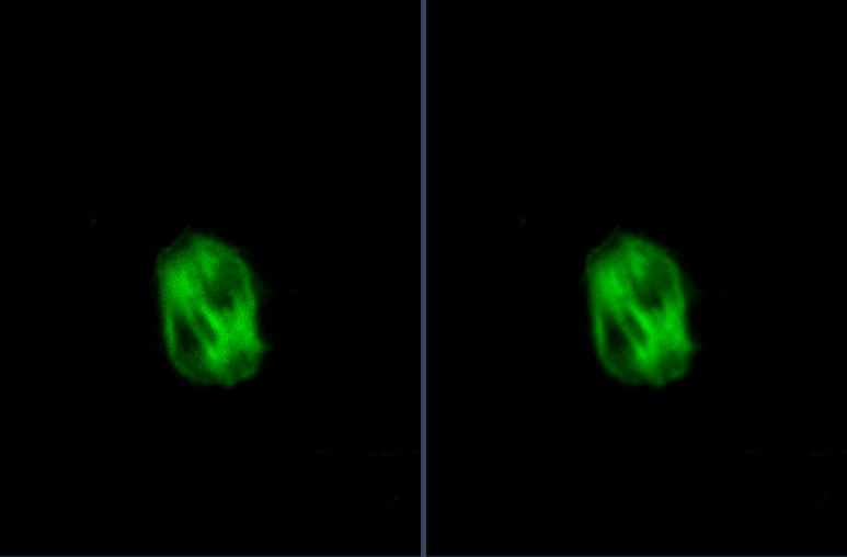
The offline software NomisPro X‑V bundled with NCF1000 laser confocal microscope provides four filtering algorithms. Mean filtering can be applied to improve image signal‑to‑noise ratio.
Figure 9: Processing interface
Figure 10: Images before and after mean‑filtering treatment
III. Common Issues Encountered in Experiments
Q1: How to quickly locate the focal plane with 60× or higher‑magnification objectives?
A1: The NCF1000 laser confocal microscope offers three Z‑axis focusing methods:
① Three‑speed focusing (low / medium / high) via focus knobs on both sides of the microscope main body. Locate the approximate focal plane at medium speed, then fine‑tune at low speed.
② Three‑speed Z‑axis focusing through the motorized joystick, following the same workflow as ①.
③ Open the “Microscope Control Panel” in software to customize focusing precision, and perform fine focal‑plane positioning with mouse scroll wheel or Z‑axis movement.
Q2: How to acquire high‑SNR spindle images using 60× or higher‑magnification objectives?
A2: During image acquisition, adjust pinhole size in software to obtain high‑SNR raw images. For 60× or higher‑magnification objectives, the recommended pinhole setting is 2‑3 Au. Laser channel intensity and gain value can also be adjusted appropriately to improve image quality.
For post‑processing, the offline NomisPro X‑V software provides four filtering modes and deconvolution algorithms to boost signal‑to‑noise ratio, selectable according to actual image conditions. Adjusting image levels is another option for SNR improvement.

 Products