I. Experimental Background
As an important research subject in biomedicine, the mouse ankle joint features sophisticated anatomical structures and physiological similarities to humans, serving as an ideal model for osteoarticular‑disease, sports‑injury and regenerative‑medicine research. This joint is precisely articulated by the distal ends of tibia, fibula and talus, with articular surfaces covered by hyaline cartilage. Its unique biomechanical properties support weight transfer and multi‑directional movement. The peripheral ligament network (lateral collateral‑ligament complex, deltoid ligament, etc.) works synergistically with tendons to maintain joint stability and enable flexible motion.
The microenvironment formed by synovial tissue and joint capsule is rich in cytokines, providing a critical research window for pathological mechanisms of inflammatory arthritis such as rheumatoid arthritis. In scientific research, this model is widely applied for:
1. Dynamic observation of osteoarthritis progression (cartilage degeneration / osteophyte formation)
2. Biomechanical evaluation of tendon / ligament injury repair
3. Validation of novel anti‑inflammatory drug‑delivery systems4. Research on stem‑cell therapy for cartilage regeneration
Combining Micro‑CT 3D reconstruction, histopathological staining and gene‑editing techniques, researchers can precisely dissect joint‑degeneration mechanisms and provide translational‑medicine evidence for diagnosis and treatment of human joint diseases. Wide application of this model in phenotypic studies of knockout mice further reveals the pivotal roles of Wnt/β‑catenin, TGF‑β and other signaling pathways in joint‑homeostasis maintenance.
In this experiment, overall inflammatory status of stained tissues is observed.
II. Experimental Scenario: Large‑image Mosaic and Observation
1. Large‑image mosaic is an important fluorescence‑analysis method. Since a single field‑of‑view cannot cover the whole sample, multiple images acquired at different positions within the target region are stitched into one single image via specific algorithms.
: Schematic diagram of large‑image mosaic
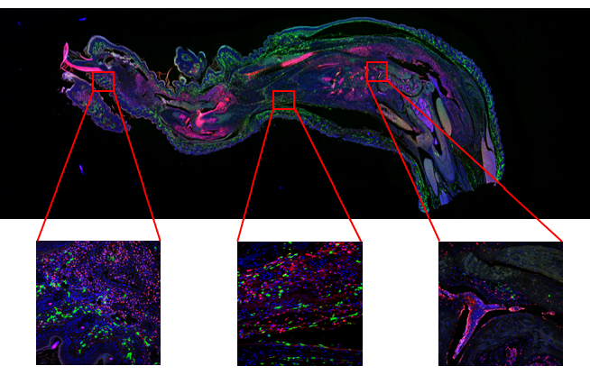
2. In this experiment, tissue samples were stained with three dyes. The large‑image mosaic function was adopted to observe the full‑range tissue. After overview observation, high‑magnification objectives were used to navigate to regions of interest for detailed inspection. Using the NCF1000 confocal microscope, the 4× objective was firstly applied for large‑field mosaic scanning. Target positions were then located, and the 20× apochromatic objective was used to capture local tissue features for assessment of ankle‑arthritis in mice.
- Observation of Global and Local Tissue Structures via Large‑image Mosaic
Normally, low‑magnification objectives such as 10× or 4× are used for global mosaic acquisition, followed by high‑magnification objectives for local‑detail imaging. For mouse‑ankle‑joint‑tissue observation in this experiment, mosaic scanning was performed with the 4× objective, and local regions were imaged with the 20× objective.
Figure 2: Global and local views of mouse ankle joint tissue No.1
Mosaic Acquisition Parameters
Microscope: NCF1000 Laser Confocal Microscope
Objective: 4× (NA = 0.15)
Resolution: 512 × 512 pixels
Laser Channels: 405 nm, 488 nm, 561 nm
Mosaic Matrix: 6 × 9
Single‑frame Acquisition Parameters
Microscope: NCF1000 Laser Confocal Microscope
Objective: 20× (NA = 0.75)
Resolution: 2048 × 2048 pixels
Laser Channels: 405 nm, 488 nm, 561 nm
III. How the NCF1000 Confocal Microscope Supports the Experiment
1. Function 1: Large‑image Mosaic
The bundled NomisPro X‑C software allows free selection of mosaic‑scan areas, and supports mosaic acquisition starting from the 4× objective.
2. Function 2: Mosaic‑image Navigation
NomisPro X‑C software automatically merges scanned tile images into one complete mosaic. The stitched image acts as a navigation map, where double‑click on any position triggers stage navigation to that spot.
3. Function 3: Multi‑channel Scanning
The NCF1000 supports multi‑channel scanning combined with mosaic acquisition and navigation. Single‑channel or multi‑channel‑fused mosaic images can be generated to visualize spatial relationships of multiple fluorescent labels across the whole sample.
IV. Common Experimental Issues
Q1: How to view stitched mosaic images and adjust brightness for individual channels?
A1: After mosaic scanning, click the corresponding file under the project folder to open it in software. If mosaic resolution is below 8192, adjust channel brightness by clicking each channel just like single‑frame images. For resolution above 8192, perform adjustments within the large‑image viewer.
Q2: How to navigate to a specific sample position after mosaic acquisition?
A2: For mosaic resolution below 8192, open the target image, click the mosaic button on the right‑hand channel panel, and select “Yes” in the pop‑up window to enable position‑navigation function. Inside the large‑image viewer, double‑click any position on the image to trigger stage navigation. Note: this function works only when the sample has just been scanned and no relative displacement occurs between sample and stage.
Q3: How to observe a specific mosaic‑image position with a higher‑magnification objective?
A3: Directly switch objectives and execute navigation on condition that no relative shift exists between sample and stage. Note: if an oil‑immersion objective is required, add immersion oil onto the objective before mosaic scanning. Adding oil after acquisition will require handling the sample, which may cause sample‑stage offset and navigation failure.

 Products